|
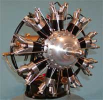
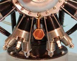
Front view of the 9 cylinder showing the general arrangement of a radial engine. Single bank of cylinders, intake and exhaust pushrods, overhead valves, exposed rocker arms, spark plugs, ignition harness and the support stand.
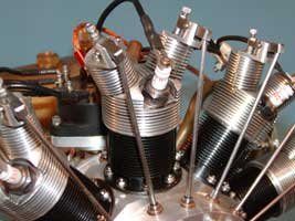
Close up of cylinder fins, valve towers, rocker arms, valve clearance adjustment screws, pushrods, valve tappets, crankcase tappet bushings, cylinder skirt bolts, spark plug and ignition wire.
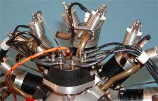
Rear view of the cylinders showing the distributor wire attachment, distributor, intake and exhaust pipe attachment to the cylinder head and the intake pipe attachment to the crankcase.
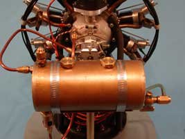
Rear view of the 9 cylinder with the distributor, carburetor, oil lines and the supply tank and hardware.
The oil sump between cylinders # 5 and # 6. Oil from the crankcase is scavenged from here and returned to the supply tank. The hex plug allows the oil to be drained from the engine
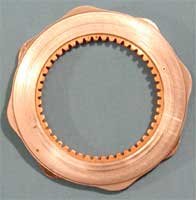
The cam is a single steel ring with an intake row and exhaust row of lobes. The internal ring gear is purchased from Boston Gear and pinned to the steel ring.
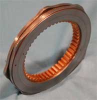
A side view of cam showing the lobes for actuation of the intake and exhaust valve tappets.
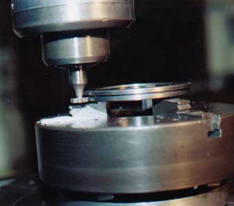
The cam intake and exhaust lobes are machined from a single set up on the rotary table using a Woodruff cutter. |